Arduino Zero/M0 Build, Upload and GDB Debugger

by Visual Micro 3. January 2016 19:32

Overview

Any visual micro project, with the android tools installed, can now run gdb debug without need for the cross platform projects used previously (still supported). For Gdb, automatic debugging can remain at default state (on).

Selecting the Arduino Zero/M0 (or board with debug.tool defined) and clicking "Debug>Start debugging" will start a GDB debug session. "Debug>Attach To Process" will start gdb without build/upload.

GDB does not yet support the special break-point commands, such as {@plot}, that can be used with the Visual Micro usb debugger.


Existing users (Projects created pre Sept 2017) please note - Older project need a minor update

The Visual Micro new project templates now contain two new properties in the .vcproj files. However existing visual micro .vcxproj files currently need to be updated manually (or deleted and re-created using "file>open>arduino project") before GDB will work.

To edit a .vcproj users can right click a project in the solution explorer then click Unload. Then right click again and click "Edit project.vcxproj". Adding the ItemGroup and PropertyGroup shown below will allow gdb to work. fyi: I added them just prior to the existing <ItemGroup> entries.

Right click the project in the solution tree and select Reload project to reload the project again.

Old .vcxproj update to support gdb. Add the following xml:-
  <ItemGroup>
    <ProjectCapability Include="VisualMicro" />
  </ItemGroup>
  <PropertyGroup>
    <DebuggerFlavor>VisualMicroDebugger</DebuggerFlavor>
  </PropertyGroup>

Key features

  • Comatible with .ino source code
  • Debug sketch, libraries and core
  • Step by Line or Instruction
  • Step Over, Step Out
  • Move instruction pointer
  • Set/move breakpoints (3 max)
  • Inspect memory, locals, call stack
  • Disassembly or source navigation
  • Immediate expression evaluator
  • Watch expressions, local expressions, auto expressions
  • Breakpoints, trace points, conditional breakpoin expressions
  • Pin variables during debug sessions. Easily see values. Add notes/comment.
  • Drill down into variables
  • Gdb command tool - optional manual interaction with the debugger (limited testing)
  • Toolchain, ocd and gdb automatic configuration based on the selected Arduino board
  • Automatic/background conversion between cpp and Arduino format .ino source code
  • Auto highlight changed data - Easily see which registers and variables have changed.
  • One button click: Build>Upload>Debug


NOTE: Compiler optimization can prevent breakpoints from becoming active.

Related Articles

Debug Arduino - Different USB Serial Port or SoftwareSerial?

by Visual Micro 26. April 2013 14:01

The project properties has an optional override of the serial port used for debug. LocalPort/RemotePort. For example LocalPort=COM10 and RemotePort=Serial2. Leave empty for the default which uses the standard Arduino usb/serial connection used for upload.

The local port relates to the pc and the remote port relates to the port the arduino will use for serial debug. Please note that some arduino boards have a single hardware Serial port, such as the Arduino Uno. Others such as the Leonardo have Serial, Serial1 and some such as the mega2560 have Serial,Serial1-4. For advanced users, LocalPort can also contain the name of a valid pre instantiated (prior to setup()) "compatible" object.

It is also possible to override the port speeds (LocalSpeed/RemoteSpeed). Normally the Remote and Local speeds will be the same unless remote devices such as xbee modules are being used.

If hardware serial port(s) are unavailble or if you prefer to debug using software serial then select “SoftwareSerial” from the RemoteTransport property.

Software serial defaults rx/tx to pins 7 and 8 but you can use the RemoteRX and RemoteTX project property to change to something else. (tip: In this case leave RemotePort empty)

It is recommended that speeds of 57k (recommended) or 19k are specified when using SoftwareSerial (especially if altering variables on a running microprocessor)

When using SoftwareSerial, leave the RemotePort property empty unless you already have a custom SoftwareSerial object in your code that you want the debugger to use (not recommended or tested).

You do not need to add the Arduino SoftwareSerial library to your project to debug using SoftwareSerial.

If you change the local port to a fixed value then that port will always be opened as a debugger after clicking F5 (or menu "Debug>Start Debugging").

If you want to use, for example, Serial2 for debug instead of the main serial port for debug then enter "Serial2" (without quotes) into the "Remote Port" property.

As stated earlier, SoftwareSerial allows you to define the pins to use for TX and RX. FastSerial works the same as HardwareSerial. To use FastSerial you must already have a project that initialises it then you can use the "Remote Port" property to define the name of the serial object. If "Remote Port" is empty then the "Serial" object is used by default

note: any property can be empty for defaults to apply

apm: If you are using the hardware serial ports of arducopter or arduplane then use the“FastSerial” option. 

How to connect arduino pins to the computer using rx and tx pins (or serial1,serial2, etc)

There are lots of different cables and usb/serial converts.

FTDI 5v Cable (there is also a 3v version)

...

(you might find it cheaper or a better alternative elsewhere)

Use the schematic to detrmine which two pins (rx and tx) to connect.

Rember to cross the rx/tx between pc and Arduino (rx>tx and tx>rx)


Control Execution Speed With Hit Counters

by Visual Micro 16. January 2013 12:00

The Arduino Debugger can be used in a more advanced mode allowing you more control over the frequency of Break and Trace control/messages. Keep in mind that behind the scenes this debugger uses serial messages. Allowing too many messages will cause either the arduino or your pc to loose or corrupt messages and a possible slow down of cpu(s).

Placing a trace point in a fast loop() would produce too many messages. For this reason Visual Micro throttles the messages and forces the arduino to slow down.

By default, Visual Micro imposes a wait of up to 80 milliseconds between breakpoints. This value can be altered using the project property called "Throttle (ms)". A value of 0 uses the current default which is 80 ms.

The Throttle is designed for new users and/or quick tests in applications that do not require the arduino to run at full speed (except for when transmitting a debugger message).

Using the Throttle is not the recommended solution!

Instead of using the Throttle, the debugger "Hit Count" facility should be used to "smooth" debugger breakpoints and/or tracepoint message. 

Depending on the frequency and position of your Arduino breakpoints you might want to ensure the Throttle is disabled. To do this you set the project property called "Throttle Enabled=False"

You will see on the options menu for each Breakpoint a menu item called "Hit Count". Normally in windows debugging the hit count is a count of how many times the point in the code has been hit. This is the same for Visual Micro except that a counter is often not very useful. Instead we can optionally switch from a count to a millisecond interval timer.

For example:- Setting the option "Break when hit is a multiple of x" to 200 would cause the arduino to break or trace when the code it hit every 200 times. However setting the project property called "Hit Counter" to milliseconds will cause the break/trace point to execute every 200 milliseconds. 

note: when using non-breaking tracepoints the stream of debug messages are processed on the pc in batches of up to 10 per second (also depends on the amount of data). The time displayed in the pc debug trace is the time each message is processed on the pc, not the time the message was sent from the micro-controller. For example, we might use a tracepoint at 4hz (every 250ms). In this case the debug data will be an accurate reflection of the micro_controller every 4hz however the millisecond values in the pc trace might not appear enitrely consitent. 

Basic Hit Counter Information

Modify Arduino Variables During a Debug Session

by Visual Micro 24. October 2012 14:57

Update Arduino MCU Variables During A Debug Session


There are three modes a breakpoint can work:

  • Disabled
    In this mode, breakpoints have no effect at all, but you can leave them in your sketch, if you want to.
  • Enabled, not halting execution
    In this mode, the breakpoint updates expression windows, trace and code windows but execution of your sketch continues without interruption.
  • Enabled, halting execution
    In this mode, when a breakpoint is hit, it halts execution of your sketch until you press [F9].

To disable Debugging/Breakpoints completely...

To enable Breakpoints...

To make breakpoints halt sketch execution when passed...

To let breakpoints continue execution of your sketch when passed...


Note 1: These settings become effective after a recompile/upload of your sketch
Note 2: These settings become effective immediately in your debugging session
Note A: These settings are global for all Visual Micro projects
Note B: These settings are project and configuration specific and apply to all breakpoints in the project
Note C: These settings are breakpoint specific


 Note:

If you chose Break/Pause = True and your sketch is halted in a breakpoint, see the link below in the "See also" section to find out how to stop the sketch at that point, recompile and upload.

Related Topics

Miscellaneous Topics

Tip: Use =? to change the value of an Arduino variable


The debugger supports two different modes that allow variables to be updated. It is important to understand the difference between the two modes:-

Mode 1) Debug with "Enable Break/Pause=False" - Arduino does not stop

In this mode we can alter any of the assigned writable variables at any time however the change in value will only be recognised when the BreaPoint/TracePoint is hit/passed. The order that variables are updated corresponds to the order that you update them. For example if you update var1 which is in a breakpoint hit every 10 minutes then no other updates will be applied to any other variables until the 10 minutes has been reached.

If you are updating variables in a fast loop() then, subject to your code, the updates should also be applied immediately.

Mode 2) Debug with "Enable Break/Pause=True" and "WhenHit Continue Execution = False" - Arduino stops and waits for F5/Continue

In this mode only the variables of the current breakpoint can be changed.

With the mouse, select and hover over a breakpoint in the expression window to see information about the breakpoint

In the image below the breakpoint configuration specifies variables 'i' and 'a' to be read/write and 'c' is read-only. This configuration is specified using the "WhenHit" property of the breakpoint. 

Update Arduino MCU Variables During A Debug Session


Arduino Debugger Extensibility Performance Considerations

by Visual Micro 7. August 2012 14:00

Aug 2012: First draft - The Visual Micro Extension Framework

Visualizations provide a simple way to build powerful fully featured graphical plugins. It is possible to code both efficient and inefficient visualizations, the latter should be void!

Unfortuately all this power and flexiblity means that it is possible to create unwieldy and slow plugins that consume fast amounts of cpu power. This document provides a place to develop useful tips and suggestions that will help ensure the debugger continues to run at an efficient speed.

The Visual Micro interface provides a number of standard events that should be used to perform a little work as possible. For example in the OnDebugInit event is called once each time a debug session starts. The event should be used to initialise as much as possibly ensuring that a timer is used when possibly to prevent blocking.

The OnDebugExpressionsChanged event is called every time a breakpoint is hit. It is a high volume message and should be used to perform as little work as possible. Off-loading heavy processing to a regulated timer using a flag is highly recommended.

This OnDebugExpressionsChanged event also procides access to the dynamic xml properties from the MicroExtensions.xml config file. Looking up xml poperties is relatively heavy on cpu load as opposed to using class variables to store property settings. For this reason it is recommended that the OnDebugExpressionsChanged event is used to copy regularly used xml config properties into class variables. This will enable functions that are called regularly during a debug session to refer to the class properties and NOT the xml config properties.

When developing .NET visualizations (UserControls and Forms) testing using the slowest possible pc is highly recommended. A good target to aim for seems to be no more than a 3% increase in cpu load on a 1.8Ghz intel processor.

You can easily test the load your extension causes by adding a "Pause" checkbox to your control or form. Stop responding to the OnDebugExpressionValuesChanged event when the checkbox is true. Start a debug session and add a breakpoint that your visualization is watching for intoto the loop().  This causes a huge amount of debug messages to be sent to the pc. Clikcing the Pause checkbox should clearly show in windows task manager the additional cpu load.

The Visual Micro Extensibility Framework

by Visual Micro 7. August 2012 11:57

Aug 2012: First draft, - About The Visual Micro Extension Framework

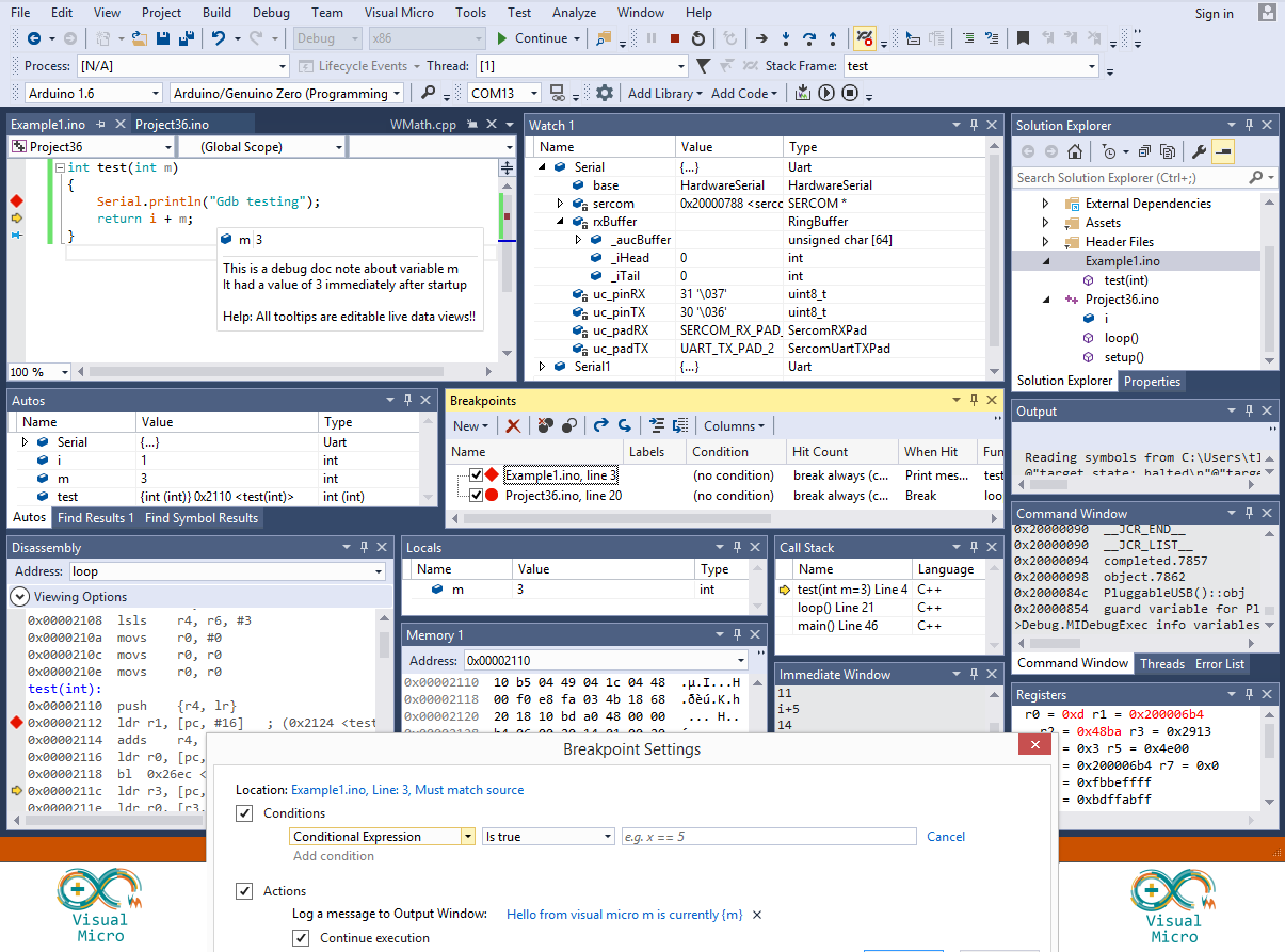
Debugger visualizations are controls and/or windows written in any .NET language that enable us to graphically display remote debug data from a micro-controller such as an arduino. This means that any open source .net instrument/control project that can be found on the internet can be used as a visualization. The micro extension framework is a set of easy to implement inheritable classes that enable an application to interact with the arduino debugger and also with visual studio. Visualizations are loaded with full trust and have access to a computer in the same way that other visual studio addins can access a computer.

The Visual Micro inheritance system is optional, but provides an easy way to manage a debug state server. Below is an example of a >NET form constructor requesting notification of 3 visual micro debugger events. (OnDebugInit, OnDebugStateChanged, OnDataExpressionValuesChanged)

public SketchDebuggerExample1Window()
{
InitializeComponent(); //standard vs component init


  • this.OnDebugInit += onDebugInit; //fires when debug is started before connect to micro
  • this.OnDebugStateChanged += onDebugStateChanged; //fires whenever a debug state change occurrs
  • this.OnDataExpressionValuesChanged += onExpressionValuesChanged; //fires when a watched expression breakpoint is hit


}

Event sigantures

  • void onDebugInit(object sender, DebugInitEventArgs e)
  • void onExpressionValuesChanged(object sender, ExpressionValuesChangedArgs e)
  • void onDebugStateChanged(object sender, DebugStateChangedArgs e)

The Visual Micro debug upgrade is supplied with a few basic working examples such as Digital Pin Viewer, Analog Graphs and other examples, found on the internet and adapted to be intelligent visualizations. All of the example are supplied with full source, attributed to the original authors, and may be feely copied or extended.

Visualizations are therefore simply just .NET dll(s) and all that is needed to register them into Visual Micro is a MicroExtension.xml file. The xml file provides a unique name for the visualization, a caption, path to the dll and namespace.className of the control to be loaded. The file also allows "Watched" expressions "of interest" to be registered and setting of the "Startup" type.


"StartUp" types include:-

  • open when watched expression is hit
  • open when debug starts
  • open when user demands

The captions of all open/running Visualizations will appear on the "Running Visualizations" menu of the debug button in the serial tool window. This menu item allows us to hide/show active visualizations for the current project. (Settings are retained after vs closes)

The captions of any "When User Demands" visualizations will appear on the "Other Windows" menu of the the debug button in the serial tool window. This menu allows us to enable/disable a visualization for the current project. (settings are retained after vs closes)

Visualizations can be placed in specific folders in any one of three locations. Under the vm program folder, under My Document, under a sketch folder. The latter being specific visualizations for a single sketch project.

To create a visualization we create a normal .net class project and set the COM Visible property to true (Project>Properties>Build>Assembly>Com Visible checkbox. Adding a UserControl or Form to the class project and inheriting MicroDebugDataVisualizationWindowBase or MicroDebugDataVisualizationControlBase

To gain access to these inheritable classes the project must contain a reference to Visual.Micro.Debugger.Data.Extensions" assembly that is available in the global assemblies list. Tip: Right click the project and select "Add Reference". Alternatively copy and rename one of the provided Visual Micro examples which will already be configured with the reference :)

  • using Visual.Micro.Debugger.Extensions
  • using Visual.Micro.Xml

The xml object is an optional helper, if you have experience with xml you might have a better solution.

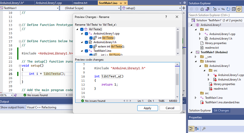
If you copy an existing Visualization we must replace the projects "Assembly" guid with a new one. Create a new guid using Tools>Create Guid. Set the new guid against the project by right clicking the project and clicking the Advaned or Assembly button

Click to enlarge. Soon to be released open source debugger visualizations. Digital and analog visualizations are included with the debugger upgrade. Build visualizations using ANY data from an Arduino

How can we debug our visualizations

Currently, the controls shipped with visual micro are .NET3.5 format so that they work for both VS 2008 and 2010 users. If you are using VS2010 and want to debug a visualization it is recommended that you switch the .NET version (project properties) to 4.0. If you do not do this then you will not be able to use "Start>debugging" in your c# or vb projects. Instead you will have to use "Tools>Attach to process" once you have an Arduino sketch open in Visual Studio. "Start>debugging" is the recommended debug option because it will allow you to edit/change your code during an active debug session.

It gets a bit confusing because to debug your visualization you will have two debug sessions running in two different visual studio instances. One for your visualization and one for the arduino :) You should also bear in mind that if you havd a sloe machine or if you hit a breakpoint in your C#/Vb code the pc will fall behind realtime with the arduino. This is not a probleme except it might cause confusion. So after breaking into a visualization and fixing a bug, I suggest re-starting the debug session.

When you try to start>debug a class project in visual studio you may encounter a message telling you that class projects can't be debugged directly. Our extension is a Visual Studio plugin so we actually want to debug visual studio when it is running our extension.

To make the debug work correctly, right click the project and open the project properties window. Click the "Debug" tab and click the radio button called "Start external program:". Enter the full path to your visual studio program in the box. An example being "C:\Program Files (x86)\Microsoft Visual Studio 10.0\Common7\IDE\devenv.exe". On the same screen, set the "Working directory:" to the folder containing the devenv.exe, an example might be "C:\Program Files (x86)\Microsoft Visual Studio 10.0\Common7\IDE\"

Once you have set .NET4 and configured the options above you can switch the visualization project to "Debug" mode and press F5. This will start visual studio so you can open a sketch project that will use the visualization. Configure the sketch for "Full" debug and press F5 to start the arduino debugger. When the visualization opens in the arduino debugger your breakpoints should be hit in the visualization control debugger.

Important Point: When a visualization has been loaded into a tool window by an instance of visual studio, the visualization (dll) will not be unloaded/released until the Visual Studio instance exists. A hidden visual studio tool window is still open and available. You will not be able to re-compile the visualization while the assembly remains loaded into another visual studio instance

Configuration Settings

Whilst a visualization dll can not be re-loaded without re-starting visual studio it is possible to alter the settings in the MicroExtension.xml which is re-loaded each time the debugger starts. This also means that is is possible to add new extensions without re-starting visual studio, Visual Micro will auto detect new xml files each time the debugger starts.

The MicroExtension.xml file also provides the facility for "User Settings" allowing the visualization to dynamically render different graphics based upon xml properties. This means that a single visualization control can be highly customizable without the need to re-compile or re-build the visualization dll.

Below is an example of a very basic visualization. The project provides 3 cicular dial instrument controls (like speedometers). When the arduino debug starts the visualization is notified and is also provided with the xml object of the MicroExtension.xml along with simple functions to provide the xml data to the c#/vb code.

The c#/vb visualization example responds to the visual micro "OnDebugInit" event and initializes its graphical controls based upon the xml properties. This means that you can create a flexible visualization control that can be used in different ways by different people or in different projects.

In the xml example below the xml is a know visual micro structure except for "ConfigSettings". This section(s) is entirely user defined but it is hoped we find and agree a standard that we can all work with.

The ConfigSettings section can be accessed in c#/vb as follows:-

  • XmlNode ConfigSettingSensor1;
  • ConfigSettingSensor1 = MicroGetVisualizationConfigSetting("Sensor1");
  • ValueExpressionNameSensor1 = XmlHelper.GetAttribute(ConfigSettingSensor1, "ValueExpressionName")

MicroExtension.Xml example follows

<MicroDebugExtension Startup="WhenHit"
Name="SketchDebugExtension1"
Caption="Sketch Debug Example 1"
Enabled="1">

  <Visualization Type="ToolWindow" 
AssemblyName="bin/SketchDebuggerExample1.dll"
FullTypeName="VisualizationExamples.SketchDebuggerExample1Window"
Startup="WhenHit">
    <Watch>
<Expressions>
<Expression Name="ValueOfDial1">analogReadingA</Expression>
<Expression Name="ValueOfDial2">analogReadingB</Expression>
</Expressions>
</Watch>

<ConfigSettings Name="Standard">
<ConfigSetting Name="Page"
FontSize="12pt"
/>
        <ConfigSetting Name="Sensor1"
DialText="Something 1"
MinValue="0"
MaxValue="1100"
NoOfDivisions="11"
NoOfSubDivisions="5"
ValueExpressionName="ValueOfDial1"/>
        <ConfigSetting Name="Sensor2"
DialText="Something 2"
DialColor="Green"
MinValue="0"
MaxValue="1200"
NoOfDivisions="12"
NoOfSubDivisions="5"
ValueExpressionName="ValueOfDial2"
/>
<ConfigSetting Name="Sensor3"
DialText="Something 3"
MinValue="0"
MaxValue="1200"
NoOfDivisions="12"
NoOfSubDivisions="10"
DialColor="Yellow"
ValueExpression="ValueOfDial3"
/>

</ConfigSettings>

</Visualization>
</MicroDebugExtension>

Arduino Debug Release Information - Breakpoints Example

by Visual Micro 19. May 2012 13:59

The Arduino debugger upgrade for Visual Studio is due for release in June 2012. The date has slipped slightly due to high work loads. The debugger includes eveything required to set conditional breakpoints, trace messages, expression reporting step through pre-defined debug points. The Arduino debug tool does not require you to make any code modifications to your arduino source code so it is fully automated.

In the Arduino breakpoints below we see 5 breakpoints of various types. Two breakpoints have conditional expressions, one breakpoint produces a trace message and also reports the value of variable i. An unlimited number of Arduino variables to watch can be set per breakpoint, the message is also optional. Two breakpoints have hit conditions (n times before each hit)

Read more about the Arduino Debug Tool

Please EMAIL beta @ visualmicro.com if you would like to be a beta tester

Configure Arduino Debugging to use Software Serial

by Visual Micro 6. May 2012 12:00

The method of "Transport" used to send or receive debug messages on the Arduino defaults to standard serial ports such as Serial or Serial1 etc. The default (empty) is "Serial" however the RemotePort project property can be altered to another port suppoted by the micro-controller.

The "RemoteTransport" project property allows SoftwareSerial and spare digital pin(s) to be used as an alternative to the built-in Serial ports. The SoftwareSerial library is automatically included duiring debug compilation if required. The RemoteTx (and RemoteRx for Debug Break/Pause/Step) project properties should be populated with the digital pin numbers used for tx/rx on the Arduino. See the arduino.cc software serial guide when choosing digital pins

To use FastSerial the project must include all required library references and the RemoteTransport project property must be set to FastSerial. Other methods of debugger "transport" can be added by advanced users. We hope that in the future debugger transport will be configurable using a simple user interface. Please ask in the forum for more information.

All of the options shown below are default except for the FastSerial setting. 

click the image for a draft debugger overview tutorial

Tips...

  • To use a different Arduino serial port such as Serial2, enter Serial2 as the "RemotePort" property
  • To use a different PC serial port such as COM7, enter COM7 as the "LocalPort" property
  • To switch from the default speed of 115200, set the "LocalSpeed" to value from the pick list, RemoteSpeed will change automatically to match.
  • Apm users should not that the "Throttle" properties relate to debugger bandwidth throttling and are nothing to do with drones :) Leave the throttle at the defaults, learn more about the throttle via the forum.
  • If using SoftwareSerial on spare digital pins you should clear the RemotePort property and set the Remote Rx Tx Pins to the digital pins that are connected to the serial device or cable. If "Break/Pause" and "Startup Wait" are not enabled (default) then only the Arduino Tx pin is required

And a few hints that might mean something at some stage...

1) Validation Skip (project property) 

Set to False if you are not altering the arduino code in a way that might cause compilation errors. This will skip the "release" build of apm that happens prior to the debug build. (Saves time)

2) TracePoint Throttle (project property)

An unconditional breakpoint/tracepoint example in the 50hz loop is a good example for us to use...

By default, for newer users and non fastserial users the breakpoints are throttled so that the 50hz loop will only run at about 8-12hz. Visual micro ensures an 80 millisecond delay between breakpoints. 

a)
FastSerial, if available, is more efficient than normal Arduino Serial therefore you could change the project property called Throttle (ms) to, for example, 30 (milllis) which would improve the speed. Leaving the Throttle (ms) empty uses the default of 80ms.

or b)
Try setting "Throttle Enabled = False" to entirely disable throttling in which case apm will send as fast as it can but it is possible for the arduino buffer to overflow causing the debug to stop working or invalid serial packets to be received by the debugger

or c)
Set the breakpoint "HitCount" to 50. Because we are in the 50hz loop this should produce one debug breakpoint message every second allowing apm to function at full speed inbetween each breakpoint message

or d)
Set the "Hit Counter" project property to milliseconds and all the breakpoint "HitCounters" will no longer be treated as counts, instead the HitCounts will represent milliseconds. So a breakpoint "HitCount" of 1000 would produce a debug  message exactly once every second regardless of where you put the breakpoint.

IMPORTANT NOTES 

When sharing the serial port with the arduino code you might expect to see some "junk" in the serial window. This is normal, the debugger windows will workaround the "junk" and function correctly. If your arduino program reads the serial port then you will not be able to switch on the break/pause facility in which case you should use a different arduino serial port or SoftwareSerial on two digital pins.

The throttle setting is very dependant on the speed of your pc. If the arduino sends messages faster than your pc can process them the pc display will fall behind the arduino. The pc display will no longer be real-time and will be confusing.

Reminder: Please read our disclaimers !!

Break Points Can Be Disabled But ...

by Visual Micro 5. May 2012 18:46

You will notice that in Visual Studio breakpoints can be disabled. Visual Micro always sends all breakpoints to the Arduino during compilation but will stop reporting disabled breakpoints.

This means you can switch on/off breakpoints during a single debug session by enabling or disabling them.

If using debug break/pause with disabled breakpoints the breakpoint will still be active in the arduino but the pc will automatically send an F5. This means that disabled breakpoints will still cause the Arduino to work more slowly than normal but that the breakpoint will not require users to manually press F5. This feature might be useful in some situations or to freeze the variables window for certain variables.

It is recommended that breakpoints are exported and/or deleted when not being used.

BreakPoint Hit Count Condition

by Visual Micro 5. May 2012 18:36

Instead of, or in combination with a conditonal breakpoint expression (as described in earlier posts) to make an Arduino trace or break point we can use the "Hit Count" dialog.

The hit count dialog is opened by right clicking any break break and selecting "Hit Count" from the menu that appears (described in detail in earlier posts). The Hit Count dialog allows us to select 4 options.

The example below is self explanatory. If we are adding a break point into a frequent arduino loop we might set a hit count of 30000. In effect this will increment a counter in the code until 3000 is reached, then the breakpoint will be executed prior to the counter being reset to 0. To use a normal "count" for a hit counter then set the project or global property "Hit Count" to "Counter". The default "Hit Count" is "milliseconds"

Tip: The hit count is automatically combined with any conditional expression (as described in earlier posts). Example, we use "break when hit count is a multiple of 250 and we set the HitCount in the project properties to milliseconds (is the default) then we will see a breakpoint or tracepoint 4 times per second (every 250 ms)

How to control the Arduino execution speed during a debug session


note: when using non-breaking tracepoints the stream of debug messages are processed on the pc in batches of up to 10 per second (also depends on the amount of data). The time displayed in the pc debug trace is the time each message is processed on the pc, not the time the message was sent from the micro-controller. For example, we might use a tracepoint at 4hz (every 250ms). In this case the debug data will be an accurate reflection of the micro_controller every 4hz however the millisecond values in the pc trace might not appear enitrely consitent. 

Break/Pause Into Source Code

by Visual Micro 5. May 2012 17:59

2015 - The following is old documentation. In many ways it does still apply but the debug features are better described in our Documentation section

The example below shows both automated and manual arduino source debugging features. The "old style" manual debug of arduino is shown in the code. Some of the automated features are shown in the "When Breakpoint hit" dialog

Individual points in your Arduino source code can be configured to break/pause or simply trace/continue without pause. The configuration settings change depending on the type of break or trace point. When a break/pause is hit Visual Studio will automatically open and select the line of arduino source that contains the current break point.

Most points can be configured to either continue or break/pause using the breakpoint message window as shown below.

Untick the "Continue Execution" checkbox to force a pause. Behind the dialog in the example we can see that the Arduino is paused on a breakpoint. Pressing F5, clicking any of the Visual Studio "Start>debug" commands or sending any serial data will re-start the Arduino program.

This example shows a few of the options that allow Arduino source code debugging

IMPORTANT WARNINGS! It is only right that we make the following statements very clearly...

Before enabling Arduino debug "break/pause" you must carefully consider what will happen if the Arduino suddenly stops on a breakpoint. Will your flying machine drop out of the sky and injure someone or be damaged. Will a robot crash? Will a motor be stuck on full power? Will a device stop responding and cause a critical problem? This is entirely your responsibility, if you are in any doubt then ask questions on the forum but please do not use this feature until there is no doubt! The same applies to the ability for the Arduino to pause at startup.

All arduino debug pause features provided in Visual Studio can not be relied upon in sensitive or dangerous siutations. This is because of the use of the serial port for the debug "continue" command. In the current version any data transmitted over the debug serial port will cause the Arduino to continue program execution which might be unexpected in many cases such as electrical interference and stray serial data.

Debug break/pause should only be used with breakpoints that will be hit every so often otherwise you will spend your time hitting F5 (continue) lots and lots of times :) If you mistakenly set a break condition that happens to often you will find that you can untick the "connect" checkbox on the serial window to stop the serial comms. This will, ineffect, stop the debug session but bear in mind that the Arduino will still be in debug mode.

Because the Arduino can be in debug mode and might be paused while Visual Studio is not in debug mode it is suggested that you either upload a "release" version when you finish debugging. This will ensure the Arduino is always in a known state. 

It is strongly recommended that you switch on the DTR setting on the serial window or in the Visual Micro options. The DTR setting will ensure that the Arduino is reset whenever  the serial window connects and/or debugging starts. Without the DTR setting it possible to start debuging when the Arduino is already paused on a beakpoint which will be confusing for most users.

Debug Break/Pause is enabled by selecting the project in the Solution Exporer and viewing the properties window (not right mouse click properties, the Property Window). Set Enable Break/Pause to True. Each time Break/Pause is enabled for a project a warning is displayed.


Optionally make use of the _DEBUG symbol in your Arduino code

by Visual Micro 5. May 2012 17:36

Nov 2012 - This document is out of date. A new prject property called Define _DEBUG allows you to enable this property in the standard plugin. The #define will be called _DEBUG

When debuging is enabled the _VMDEBUG symbol allows code to be used "instead of" or "in combination with" the Visual Studio debug tools

The example below shows the wrong name for this symbol


Share The Arduino Serial Port With The Debugger

by Visual Micro 5. May 2012 17:16

The example below shows a single Arduino Serial Port being used for both debug and static serial messages.

The example goes one step further by making use of the DEBUG symbol allowing the static messages to only be included in the program when debuging is enabled for the project.

Notes

In the example above the code in the Serial.begin() in the setup() function is not required because both the debugger and the project are using the same port. However, if the defined(DEBUG) condition is removed from the code then Serial.begin() would be required. Therefore it is safer to add Serial.begin() if your sketch code directly uses the Serial port.

The same would apply if the debug "Remote Port" on the project properties was set to a port other than "Serial". In this case you would certainly need to initialise the Serial port.

Optional Message Viewers

by Visual Micro 5. May 2012 16:47

Visual Studio provides a number of text message views during a arduino debug session. Configuration of which windows are used to view messages is available using the debug options sub menu on the active debugger Serial window as shown below.

Messages can be directed to any combination of 3 windows:-

  • Serial Viewer
  • Message Viewer
  • Trace Viewer

The example above would allow messages to be appear in a dedicated message window (as shown below) and also in the trace window (as shown in previous posts).

Below shows a "message only" window which is free of trace messages

Below shows a "trace only" window which is free of messages. The example below was created by unticking the "Trace" sub menu shown at the start of this post.

Running Variables and Expressions Viewer

by Visual Micro 5. May 2012 16:40

In addition to showing hit data the "Variables and Expressions Window" provides a number of additional columns that are enabled by right clicking the list (as shown below)

As with all Visual Micro windows, the Arduino Debugger Variables Window can be docked. The window positions are retained on a "port by port" basis and scrolling locks the variables/expression name column to provide clearer analysis

During Arduino program debug, variables and expressions are automatically displayed inside a grid grouped by breakpoint location. Double clicking a variable of breakpoint will jump to the respective line of source code

Source Code Modification Tracking

by Visual Micro 5. May 2012 16:24

A debug session continues on the Arduino until a release program/sketch version is upload therefore it is possible for the source code to be different from the source code running on the Arduino. For this reason breakpoint configuration and source code is saved during compilation and used to display messages and variable data during debug.

Tip: Hovering over the name of a breakpoint provides a summary of the code that was uploaded to the Arduino. In the example below we see that the Arduino is using a random number between 0 and 2000 when the code has been altered to between 0 and 4000


Conditonal Breakpoints and Tracepoints

by Visual Micro 5. May 2012 15:25

If we need to debug fast running arduino code we might only want to trace exceptions or conditions within a certain range. Visual Micro allows any expression to be used as an arduino breakpoint condition.

To add a debug conditon to an arduino breakpoint we can use the right menu menu to select the breakpoint options menu. it is also possible to set a "Hit Count" allowing a tracepoint to be reported every x times that it is executed (hit) by the arduino cpu.

The example below shows an arduino debugger tracepoint that reports when a random number of between 0 and 2000 has a value between 1000 and 1500. The debugger tracepoint reports the value of i and also the value of the Arduino millis() (milliseconds since startup). "Is True" or "Has Changed" may be used to distinguish between the type of condition that is required. In each case the expression entered must either return boolean true/false or a value. The example below uses the "Is True" condition to ensure the value of i is within the given range.


The image below shows this conditional tracepoint when an arduino is running in debug mode. Notice the variables viewer displays both variable and expression along with min and max values. In the example below the min and max values of the condition have already been reached. 

Items in red show data that has changed since the last point was hit.

Trace Messages and Variables/Expressions

by Visual Micro 5. May 2012 14:30

Right mouse clicking a debugger break point in the source code or in the debugger Breakpoints Window (CTR+ALT+B) provides a number of menu items relevent to the breakpoint.


Clicking the debug "When Hit" option opens the following dialog window allowing us to optionally print a message that includes variable data or we can just report variables to the debug tool. Debugger messages can be as long as is needed because they are not compiled into the Arduino program. Messages are stored locally on the pc and displayed when a break or trace point is hit.

The example below shows how to create a dynamic trace message that includes variable data. Note that requests for variable data are enclosed in {brackets}. Any expression that returns a numeric (int, float etc) value is allowed and any number of expressions can be included in the message. The "Run Macro" option will be supported in future versions of Visual Micro. The "Continue Execution" feature is only relevent if "Debug Break/Pause" is enabled.

After making changes to arduino debugger breakpoints or source code the project must be compiled and uploaded. The easiest way is to press F5


If the debug message soley consists of expressions (no text) then a trace message entry is not displayed. The variable/expression inspector shown below will automatically open when a debug session starts.

Double click arduino debugger variables and/or trace message to jump to the respective source code line.


Basic Trace Point

by Visual Micro 5. May 2012 14:11

When debuging has been enabled for a configuration a debug session can be started by pressing F5, clicking menu item "Debug>Start With Debugging" or the standard "Start Debugging" icon on the Visual Studio tool bar.

The first thing to note is that two compilations are performed. The first is normal compilation of the sketch to ensure it is free of errors then the second to include debug information. Below you can see the difference in memory between a release and debug build. The difference would be smaller if our test sketch already referenced the serial port and other basic arduino properties. Therefore this example probably represents a worst case senario.

If the serial port monitor was already open prior to upload then Visual Studio automatically displays the debug trace window. Otherwise the serial port monitor should be opened for the trace window to be displayed. The example below shows a running tracepoint. In a real world project we might have multiple break or trace points. Double clicking the trace point will jump to the correct line in the source code.

Creating a Simple Arduino Debug Tracepoint

by Visual Micro 5. May 2012 09:09

In this example we create a simple debug trace point using the main Arduino serial port and the default Visual Micro settings. This article assumes that arduino debugging in Visual Studio has been enabled (see this post for a how to).

The Visual Studio Debugger Breakpoints Window is opened using CTRL+ALT+B or by clicking the menu item Debug>Windows>Breakpoints. Alternatively you can right mouse click the tool bars and show the "Debug" bar as shown below above the source code.

In the example below the breakpoints window is displayed below the source code. A single breakpoint has been added by clicking the left margin of the source.

During compilation - How are breakpoints added to a temporary copy of the code?

During compilation, breakpoints are added to the end of the selected code line, can not be added to comment lines but can be added to empty source lines. Adding breakpoints to empty source lines is recommended because it ensures you are happy with the exact position the debug code will be added to a copy of the code. For example, consider the following line of code:-

if (foo) {a=0;}

In the above example the debug engine would compile the following code which involves a significant code change and might, in a more complex example, lead to unexpected results. The debug engine tries a few tests to attempt a code injection and might fail or produce the wrong code. Hence the rule, add breakpoints to empty or simple lines of codes.

if (foo)
{
a=0;
//some debug commands will be inserted here
}

SUGGESTION: Add debugger breakpoints to empty or simple lines of codes, see why at the end of this section