Analog IO is different to the IO as they support a wide number of states (255 / 1024 or more depending on your board), instead of the two supported by Digital pins.
Analog Inputs
These are often clearly marked on your board, and are commonly labelled with an 'A' (e.g. A0,A1,A2 etc..)
The same issues as experienced with digital pins floating is seen with analog inputs, so pull up (internal often available) / down resistors should be used appropriately, and the readings are representative of the voltage read on the pin.
The readings can be mapped to the voltage using the below formula:
e.g. 0-1023 reading on 5v Arduino Uno
voltage = reading * (5.0 / 1023)
To configure an input, we do not need to call pinMode(), and can simply perform the analogRead(pinNum) call to obtain the value.
Analog readings take longer than digital readings, due to how the Digital to Analog Converter works on-board, but this is still only a few milliseconds.
Analog Outputs
Using our wide range of values on the analog scale, we can use this to drive an output in a more incremental fashion, allowing for fading of an LED for example. This is achieved using PWM, and the analogWrite() function gives us an easy way to access this.
Pulse Width Modulation - the board can only output 0v or 5v, so to give the effect of an incremental voltage, the pin is turned on and off rapidly, with the width of each pulse varying, to deliver less or more power in increments.
These pins are generally clearly on your board, and will be Digital Pins, often with a '~' to denote they are PWM compatible.
Again there is no need to call pinMode() to access the analogWrite() functionality, and it needs supplying with the pin and the analog value to write.
In the Fade Example we see how this can be used to fade the LED in and out using analogWrite.
Handling Analog Input Data
The readings from your analog pin will still vary if read very often in quick succession.
If we were sensing whether we had hit a threshold, to turn an LED on, it may end up turning on and off rapidly when it is near the threshold (due to the inaccuracies of the readings). To avoid this, and to stabilise the readings we will need to average out a number of readings.
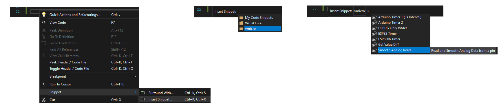
A code snippet has been included in Visual Micro to save you needing to write this code, simply right click within a function, and select Snippets > Insert Snippet. Select the vMicro folder and then the "Smooth Analog Read" Snippet.
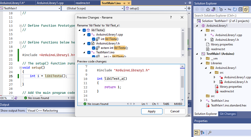
This will add a function into your code, which you can pass the pin, number of readings, and interval between them in, and it will return the smoothed value from those settings.