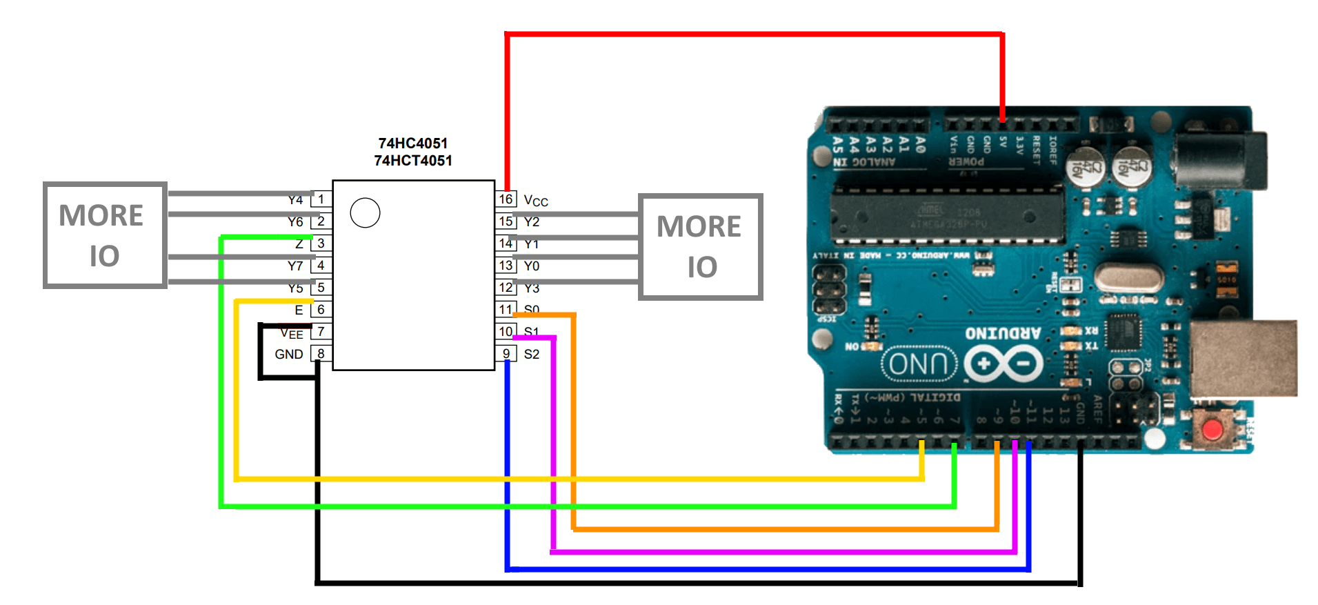
As your Arduino projects grow, you often find you need to wire in additional circuits and chips to extend the functionality of your board.
What Is It?
A Multiplexer IC allows you to interface a number of pins, with a single pin, by using a set of state pins to determine which ones are connected.
e.g. you could have 8 LEDs as Outputs, all controlled from a single output.
You could also have 8 different switches as Inputs, which are all interfaced to a single input.
Why Use It?
These ICs are similar to shift registers in their benefits, but without the need to pulse all of the data to the register in this case.
A Short Guide
e.g. 74HC4051N [Datasheet]
Output Note - Check the datasheet for your chip, as these often only allow small current draw, which can be easily stepped up to higher output powers using transistors, relays, or a Line Driver IC.
To switch between the 8 different multiplexed pins on the chip, there is a simple truth table of values employed, using S0,S1 and S2 as bits essentially.
To keep the example simple we have just used an array of values, but you could store a single byte and read the bits from it when writing it out.
| E | S2 | S1 | S0 | I/O Connected to Z |
| L |
L |
L |
L |
Y0 |
| L |
L |
L |
H |
Y1 |
| L |
L |
H |
L |
Y2 |
| L |
L |
H |
H |
Y3 |
| L |
H |
L |
L |
Y4 |
| L |
H |
L |
H |
Y5 |
| L |
H |
H |
L |
Y6 |
| L |
H |
H |
H |
Y7 |
| H |
X |
X |
X |
None |
Wiring
| Symbol | Pin | Description |
| E |
6 |
enable input (active LOW) |
| VEE |
7 |
supply voltage |
| GND |
8 |
ground supply voltage |
| S0, S1, S2 |
11, 10, 9 |
select input |
| Y0, Y1, Y2, Y3, Y4, Y5, Y6, Y7 |
13, 14, 15, 12, 1, 5, 2, 4 |
independent input or output |
| Z |
3 |
common output or input |
| VCC |
16 |
supply voltage |

Coding
We have a simple code example, using this to illuminate a sequence of LEDs. It can also be used for inputs in the same manner, making it a useful tool to switch between multiple devices and sensors without using as many pins on the board.
Download the Example here.