About the Serial Monitor Window
You can use the Serial Monitor Window to send data via the
serial
connection to your Arduino board and to visualize incoming data from your board.
With the Serial.print() and Serial.read() functions, you can send and
receive data via the serial port. Visual Micro's Serial Monitor is
the PCs counterpart on the other end of the serial line.
You can find the documentation of the Serial... functions on the
Arduino web
site.
To show the Serial Monitor in your IDE, choose vMicro > Serial Monitor or click the Serial Monitor button in the
Arduino Communications toolbar:

With the selection box
 you choose the COM port your board is connected to.
A good start for experimenting with Arduino's Serial
functions is the
ReadASCIIString example provided by the classic Arduino IDE.
(read
this page about
how to open examples)
Anatomy of the Serial Monitor window
Sending and receiving data
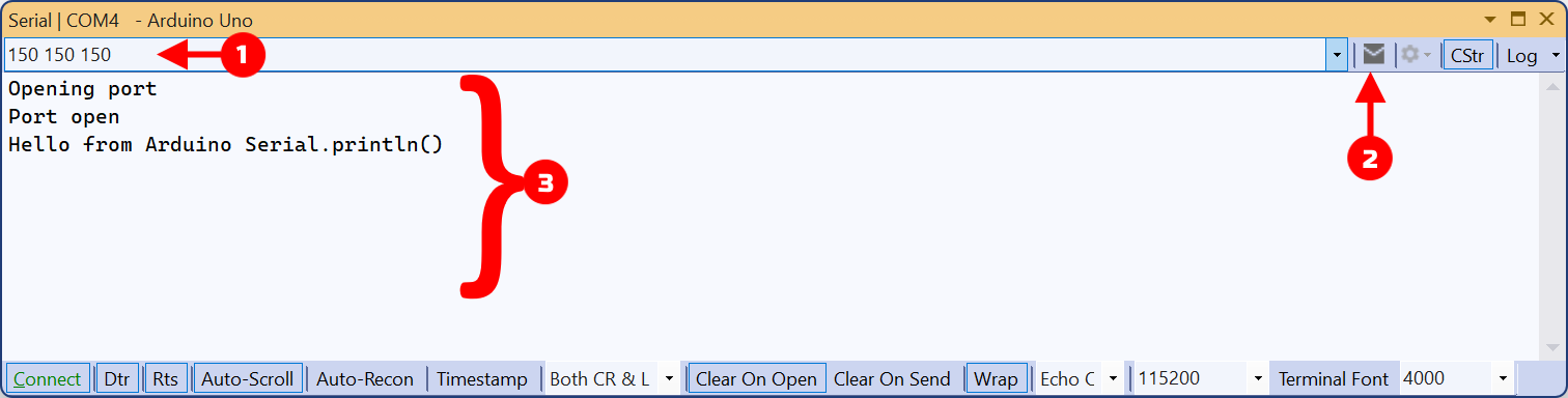
In the Outbound Area 1 you can enter characters. As soon as
you click on the Send Button 2 , the string is sent to your
Arduino board and can be
received by the board via a Serial.Read() function.
Strings received from your board are displayed in the Inbound Area 3 .
Settings and other functions
The other elements of the Serial Monitor window are important to configure
and control the serial connection.
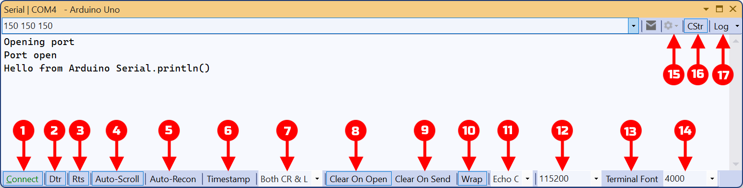
1 Connection
button
By activating/deactivating this box, you
can establish or interrupt the connection to your board. When the
connection is interrupted, then the serial port is free for other programs on
your PC.
If you
activate this box again, the connection will be restored. The behavior of your
Arduino board
depends on
the DTR checkbox (see below).
2 DTR
button
The DTR line of your board's UART is used to reset the board and restart the sketch. If
this box is activated (highlighted),
Visual Micro controls the DTR line which
results in a board reset if the board connection is established/restored (with
the "Connect" box above). The DTR switch has no effect if you use
SoftwareSerial as the transport method, see "
Advanced Serial Communication".
The DTR switch also has no effect with some boards that have a
separate small processor for serial communications.
3 RTS
button
If this box is checked, Visual Micro
can start/stop incoming data to avoid buffer overruns with high data
rates/slow PCs, by controlling the COM port's Rts line.
4 "Auto-Scroll" button
If
activated, the inbound window scrolls as data arrives. You can
also click into the inbound window to temporarily disable pause the
display and disable scrolling. Move the cursor to the end of the
window to restart display.
5 "Auto-Recon" button
If
activated, Visual Micro attempts to reconnect automatically when hardware is plugged in and/or becomes available.
Shows the connection state of the board in real-time by showing the
"Connect" button's text in green or red:  /
/  .
Some types of ports do not support this feature.
.
Some types of ports do not support this feature.
Only available in the Pro Version of Visual Micro.
6 "Auto-Clear"
button
When this box is activated, the inbound area of the window will be cleared
every time the port is reopened.
7 Echo
settings
This setting can be used to route all incoming data from one board
to another board connected to a different COM port.
Example: If you have two boards attached to your PC, one on COM3 and one
on COM4, and you choose "COM4" in the Serial Monitor of COM3, then all
data coming in from COM3 will be displayed in the Serial Monitor and
sent to the other board via COM4.
8 Line
end settings
Specifies how the string is terminated that you send to your Arduino board
after clicking the Send Button.
"no line endings": no character is appended to the
string being sent.
"Carriage return": a Carriage Return character
('CR'=0x0d or '\r') is appended.
"Line Feed": a Line Feed character
('LF'=0x0a or '\n') is appended.
"Both CR & LF": both a CR and a LF character are
appended.
The right setting depends on how your sketch handles the incoming
characters. In the Arduino ReadASCIIString example, you will notice
that the sketch waits for a '\n', which is a "newline" or "Line
Feed". So for this sketch, the "Line Feed" setting will be the right
one. If in doubt, use the "Both NL and CR" setting.
Line end characters are a convenient and common way of indicating
your board the end of a transmission.
9 Baud Rate Settings
Specifies the transmission speed or so called "baud rate" that
Visual
Micro and your board use. This setting must match the setting your
sketch uses in the
Serial.begin()
function.
If the baud rates of your board and Visual Micro don't match, you
will see no incoming characters or garbage.
If you are using
Visual Micro debugging, then this value must
also match the baud rate setting you chose for debugging communication,
see "
Debugging with Different Ports, Pins and Speeds".
The Options Menu Button 10

See here for a description
of this button's menu items.
The "CStr" Button 11

The CStr switch is only available
to users of the Visual Micro Pro version.
This is an On/off toggle switch.
If switched on, then the Serial Monitor outbound text box supports escape
sequences, similar to those used in C++ and C#, and shows them as
2-character sequences, starting with a '\':
The supported escape sequences are:
| \0 |
NUL character (value 0) |
| \a |
"Bell" character (value 07) |
| \b |
Backspace character (value 08) |
| \t |
Tab character (value 09) |
| \n |
Newline character (value 10 dec, 0x0a hex) |
| \n |
"Vertical tab" character (value 11 dec, 0x0b hex) |
| \n |
"Form feed" character (value 12 dec, 0x0c hex) |
| \r |
Carriage return character (value 13 dec, 0x0d hex) |
| \\ |
Backslash character '\' |
\xnn
\x00nn |
A single, one byte character with the hexadecimal value of 0xnn
It is recommended to use the \x00nn variant of this
notation, to avoid that characters following the sequence are
traeted as being part of the hex code, like in "\x4fa", which would
not result in '\x4f', followed by an 'a', but as an illegal
character of value 0x4fa, which will be converted to a '?' by
Visual Micro. |
\u00nn
\U000000nn |
Identical to \xnn |
The \x..., \u... and \U... only support the ASCII
character value range from 0x0 through 0x7f.
If you are working with such special characters,
and you send them to devices like an LCD display: Please keep in mind
that it depends on the device, if and how these characters are interpreted.
E.g. typical 2- or 4-line LCD displays do not understand \n as a new
line character. In this example, it is up to your sketch to send the
right commands to the LDC controller, in order to advance to the next
line.
This is also true for Non-ASCII-characters above 0x80, where devices may
have their very own character sets.
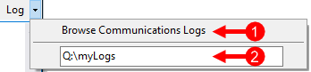
The Log Button 12
 /
/

The Serial Window writes sent and received data to a log file.
When you click on the button itself, you can switch logging on:
and off:
.
if you click on the submenu arrow on the button's right side, the Log
submenu appears, where you can specify in which folder log files shall be written (2), and you can
open this folder for opening and reviewing log files (1).
The Most Common Mistakes
When Using Serial Connections
These are the most common causes for problems with serial communication:
Wrong baud rate selected
Make sure that the baud rate in your sketch is the same as selected in the
Serial Monitor of Visual Micro. If both do not match, you won't be able
to read and write characters to and from the serial connection.
Serial.begin() missing
You cannot perform any serial reading or writing operation unless you call
Serial.begin() in your sketch. Usually, Serial.begin() is put into the setup() function of your
sketch.
Wrong port on the Arduino board chosen
With boards that have multiple serial ports, like the Arduino Due, you must
make sure that you work with the correct port in your sketch and that you have
connected this port to your PC.
Wrong serial port selected on PC
If you connect your board to different USB connectors of your PC or if you
use a different board, the COM port number may change. In these cases you must
adjust the COM port setting in the Visual Micro
Arduino Communications toolbar.
What is a COM port?
The CPUs used in most boards have one or more built in serial
communication devices called
UARTS. They work according to the RS-232 standard. The USB hardware on
the board converts these signals into similar USB signals. On the PC side, the
opposite takes place: a driver receives the USB signals, and mimics a
RS-232 hardware interface in your PC, that's why these drivers are called "Virtual
Com Port Drivers", because they are no read serial ports, but they
simulate them.
From a PC application's perspective, everything looks as if the UART of
your board's CPU was directly connected to a RS-232 connector in your PC.
Traditionally,
serial ports in PCs are called COM ports and numbered COM1, COM2 etc.
As a consequence, you can use any software that is able to
communicate via
COM ports for communication with your board, not just Visual Micro or
the Arduino IDE.