The Serial Monitor Window
You can use the Serial Monitor Window to send data via the
serial
connection to your Arduino board and to visualize incoming data from your board.
With the Serial.print() and Serial.read() functions, you can send and
receive data via the serial port. Visual Micro's Serial Monitor is
the PCs counterpart on the other end of the serial line.
You can find the documentation of the Serial... functions on the
Arduino web
site.
To show the Serial Monitor in your IDE, choose Tools > Visual
Micro > Serial Monitor or click the Serial Monitor button in the
Arduino Communications toolbar:

With the selection box
 you choose the COM port your board is connected to.
A good start for experimenting with Arduino's Serial
functions is the
ReadASCIIString example provided by the classic Arduino IDE.
Anatomy of the Serial Monitor window
Sending and receiving data
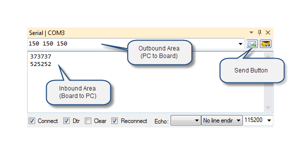
In the Outbound Area you can enter characters. As soon as
you click on the Send Button, the string is sent to your
Arduino board and can be
received by the board via a Serial.Read() function.
Strings sent by your Arduino board are displayed in the Inbound Area.
Settings and other functions
The other elements of the Serial Monitor window are important to configure
and control the serial connection.
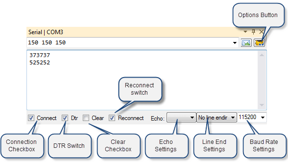
Connection Checkbox
If you uncheck this box, the connection to your board will be
interrupted. The serial port is then free for other programs on
your PC.
If you check that box again, the connection will be restored. The behavior of your
Arduino board
depends on
the DTR checkbox (see below).
DTR Switch
The DTR line of your board's UART is used to reset the board and restart the sketch. If
this box is checked,
Visual Micro controls the DTR line which
results in a board reset if the board connection is established/restored (with
the "Connect" box above). The DTR switch has no effect if you use
SoftwareSerial as the transport method, see "
Advanced Serial Communication".
The DTR switch also has no effect with some sorts of boards that have a
separate small processor for serial communications.
"Clear" Checkbox
Check this box to clear the contents of the Inbound box where the
data sent by the Arduino board is shown.
When this box is checked, the inbound area of the window will be cleared
every time the port is reopened.
"Reconnect" Switch
Indicates whether Visual Micro attempts to
reconnect to the board once it was disconnected. The initial state of
this switch is taken from Tools > Options
> Communications > Auto Re-Connect.
Echo Settings
This setting can be used to route all incoming data from one board
to another board connected to a different COM port.
Example: If you have two boards attached to your PC, one on COM3 and one
on COM4, and you choose "COM4" in the Serial Monitor of COM3, then all
data coming in from COM3 will be displayed in the Serial Monitor and
sent to the other board via COM4.
Line End Settings
Specifies how the string is terminated that you send to your Arduino board
after clicking the Send Button.
"no line endings": no character is appended to the
string being sent.
"Carriage return": a Carriage return character
('CR'=0x0d or '\r') is appended .
"Newline": a newline aka Line Feed character
('LF'=0x0a or '\n') is appended .
"Both NL and CR": both a CR and a newline (LF) character are
appended .
The right setting depends on how your sketch handles the incoming
characters. In the Arduino ReadASCIIString example, you will notice
that the sketch waits for a '\n', which is a "newline" or "line
feed". So for this sketch, the "Newline" setting will be the right
one. If in doubt, use the "Both NL and CR" setting.
Baud Rate Settings
Specifies the transmission speed or so called "baud rate" that
Visual
Micro and your board use. This setting must match the setting your
sketch uses in the Serial.begin() function. In the Arduino
ReadASCIIString example, the sketch operates with a setting of 9600.
If the baud rate of your board and that of Visual Micro don't match, you
will see no incoming characters or garbage only.
If you are using
Visual Micro debugging, then this value must
also match the baud rate setting you chose for debugging communication,
see "
Debugging with Different Ports, Pins and Speeds".
The options button

See here for a description
of this button's menu items.
The most common mistakes when using serial connections
These are the most common causes for problems with serial communication:
Wrong baud rate selected
Make sure that the baud rate in your sketch is the same as selected in the
Serial Monitor of Visual Micro. If both do not match, you won't be able
to read and write characters to and from the serial connection.
Serial.begin() missing
You cannot perform any serial reading or writing operation unless you call
Serial.begin() in your sketch. Usually, Serial.begin() is put into the setup() function of your
sketch.
Wrong port on the Arduino board chosen
With boards that have multiple serial ports, like the Arduino Due, you must
make sure that you work with the correct port in your sketch and that you have
connected this port to your PC.
Wrong serial port selected on PC
If you connect your board to different USB connectors of your PC or if you
use a different board, the COM port number may change. In these cases you must
adjust the COM port setting in the Visual Micro
Arduino Communications toolbar.
What is a COM port?
The CPUs used in most boards have one or more built in serial
communication devices called
UARTS. They work according to the RS-232 standard. The USB hardware on
the board converts these signals into similar USB signals. On the PC side, there is
a driver that can send and receive such USB-RSR-232 signals and that mimics a
RS-232 hardware interface in your PC, that's why these drivers are called "Virtual
Com Port Drivers".
From a PC application's viewpoint, everything looks as if the UART of your board's CPU was
directly connected to a serial hardware interface in your PC.
Traditionally,
serial ports in PCs are called COM ports and numbered COM1, COM2 etc.
That's why you can use any software that is able to work with
COM ports in order to read and write data to and from your board.